55 Results
View results:
Sort by:

This article presents the basic concepts in structural dynamics and their role in the seismic design of structures. Great emphasis is given to explaining the technical aspects in an understandable way, so that readers without deep technical knowledge can gain an insight into the subject.

The National Building Code of Canada (NBC) 2020 Article 4.1.8.7 provides a clear procedure for earthquake methods of analysis. The more advanced method, the Dynamic Analysis Procedure in Article 4.1.8.12, should be used for all structure types except those that meet the criteria set forth in 4.1.8.7. The more simplistic method, the Equivalent Static Force Procedure (ESFP) in Article 4.1.8.11, can be used for all other structures.

The response spectrum analysis is one of the most frequently used design methods in the case of earthquakes. This method has many advantages. The most important is the simplification: It simplifies the complexity of earthquakes so far that the design can be performed with reasonable effort. The disadvantage of this method is that a lot of information is lost due to this simplification. One way to moderate this disadvantage is to use the equivalent linear combination when combining the modal responses. This article explains this option by describing an example.

For the stability verification of members using the equivalent member method, it is necessary to define effective or lateral-torsional buckling lengths in order to determine a critical load for stability failure. In this article an RFEM 6-specific function is presented, by which you can assign an eccentricity to the nodal supports and thus influence the determination of the critical bending moment considered in the stability analysis.

The Steel Joist Institute (SJI) previously developed Virtual Joist tables to estimate the section properties for Open Web Steel Joists. These Virtual Joist sections are characterized as equivalent wide-flange beams which closely approximate the joist chord area, effective moment of inertia, and weight. Virtual Joists are also available in the RFEM and RSTAB cross-section database.

This article will show you the Building Model add-on, which has been enhanced with one important advantage: calculating the center of mass and center of rigidity.

The “Modal Analysis” add-on in RFEM 6 allows you to perform modal analysis of structural systems, thus determining natural vibration values such as natural frequencies, mode shapes, modal masses, and effective modal mass factors. These results can be used for vibration design, as well as for further dynamic analyses (for example, loading by a response spectrum).

Given that realistic determination of the soil conditions significantly influences the quality of the structural analysis of buildings, the Geotechnical Analysis add-on is offered in RFEM 6 to determine the soil body to be analyzed.
The way to provide data obtained from field tests in the add-on and use the properties from soil samples to determine the soil massifs of interest was discussed in Knowledge Base article “Creation of the Soil Body from Soil Samples in RFEM 6”. This article, on the other hand, will discuss the procedure to calculate settlements and soil pressures for a reinforced concrete building.

The stand-alone program RSECTION is at your disposal for determining section properties and performing stress analysis for thin-walled and massive cross-sections. The program can be connected to both RFEM and RSTAB so that sections from RSECTION are also available in the RFEM and RSTAB library. Likewise, internal forces from RFEM and RSTAB can be imported into RSECTION.

You can use the stand-alone program RSECTION to determine the section properties for any thin-walled and massive cross-sections, as well as to perform a stress analysis. The previous Knowledge Base article titled "Graphical/Tabular Creation of User-defined Cross-sections in RSECTION 1" discussed the basis of defining cross-sections in the program. This article, on the other hand, is a summary of how to determine the section properties and perform a stress analysis.

Modal analysis is the starting point for the dynamic analysis of structural systems. You can use it to determine natural vibration values such as natural frequencies, mode shapes, modal masses, and effective modal mass factors. This outcome can be used for vibration design, and it can be used for further dynamic analyses (for example, loading by a response spectrum).

RSECTION 1 is a stand-alone program for determining section properties for both thin-walled and massive cross-sections, as well as for performing a stress analysis. In addition, the program can be connected to both RFEM and RSTAB: sections from RSECTION are available in the RFEM/RSTAB libraries, and internal forces from RFEM/RSTAB can be imported into RSECTION.

The stability checks for the equivalent member design according to EN 1993-1-1, AISC 360, CSA S16, and other international standards require consideration of the design length (that is, the effective length of the members). In RFEM 6, it is possible to determine the effective length manually by assigning nodal supports and effective length factors or, on the other hand, by importing it from the stability analysis. Both options will be demonstrated in this article by determining the effective length of the framed column in Image 1.

The new RFEM software generation provides the option to perform stability design of tapered timber members in line with the equivalent member method. According to this method, the design can be performed if the guidelines of DIN 1052, Section E8.4.2 for variable cross-sections are met. In various technical literature, this method is also adopted for Eurocode 5. This article demonstrates how to use the equivalent member method for a tapered roof girder.

The add-on modules for designing structural member components according to national, European, and international standards also show design results in addition to numerical output in tables graphically, as diagrams displayed on the framework.

The number of National Annexes for Eurocode 2 with regard to the design of reinforced concrete cross-sections has been extended since SHAPE-MASSIVE 6.54. Therefore, the following NAs of EN 1992-1-1:2004 + AC:2010 are available:

In RF-/STEEL EC3, sets of members are calculated according to the General Method (EN 1993-1-1, Cl. 6.3.4) together with the stability analysis. To do this, it is necessary to determine the correct support conditions for the equivalent structure with four degrees of freedom. In most 3D models today, you can quickly lose track of the location of a set of members in the system.

The SHAPE‑THIN and SHAPE‑MASSIVE cross-section programs are suitable for determining the cross-section properties of common thin-walled or thick-walled sections. These cross-section properties are also available for further analyses in RSTAB and RFEM.

For the stability design of members and sets of members with a uniform cross-section, you can use the equivalent member method according to EN 1993-1-1, 6.3.1 to 6.3.3. However, as soon as a tapered cross-section is available, this method can no longer be used, or only used to a limited extent. The RF-/STEEL EC3 add-on module can automatically recognize these cases and switch to the general method.
Structures react differently to wind action depending on stiffness, mass, and damping. A basic distinction is made between buildings that are prone to vibration and those that are not.

RF-/DYNAM Pro - Equivalent Loads allows you to determine the loads due to equivalent seismic loads according to the multi‑modal response spectrum method. In the example shown here, this was done for a multi‑mass oscillator.
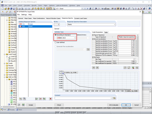
The National Building Code of Canada (NBC) 2015 Article 4.1.8.7 provides a clear procedure for earthquake methods of analysis. The more advanced method, the Dynamic Analysis Procedure in Article 4.1.8.12, should be used for all structure types except those that meet the criteria set forth in 4.1.8.7. The more simplistic method, the Equivalent Static Force Procedure (ESFP) in Article 4.1.8.11, can be used for all other structures.

The response spectrum analysis is one of the most frequently used design methods in the case of earthquakes. This method has many advantages. The most important is the simplification: It simplifies the complexity of an earthquake to such an extent that an analysis can be carried out with reasonable effort. The disadvantage of this method is that a lot of information is lost due to this simplification. One way to mitigate this disadvantage is to use the equivalent linear combination when combining the modal responses. This article explains this option by describing an example.

In order to consider inaccuracies regarding the position of masses in a response spectrum analysis, standards for seismic design specify rules that have to be applied in both the simplified and multi-modal response spectrum analyses. These rules describe the following general procedure: The story mass must be shifted by a certain eccentricity, which results in a torsional moment.

The wind load of rectangular rounded structural components is a complex matter. The equivalent forces from wind load depend on the strength of the circulating wind load and the component geometry.

In RF-DYNAM Pro - Equivalent Loads, the equivalent seismic loads can be calculated according to different standards. By calculating the equivalent loads for each eigenmode, it is not directly possible to obtain the transversal shear for each story to perform an analysis afterwards. The following example describes the option to calculate the transversal shear quickly and efficiently.
![Spectral Acceleration Sa [m/s²] Versus Natural Frequency f [Hz] of Narrow-Band Response Spectrum According to EN 1998-1 [1]](/en/webimage/009251/2417757/01-en-png.png?mw=640&hash=c76563b459152b19c98197ea6ba342be89d9a5bc)
In a multi-modal response spectrum analysis, it is important to determine a sufficient number of eigenvalues of the structure and to consider their dynamic responses. Regulations such as EN 1998‑1 [1] and other international standards require activation of 90% of the structural mass. This means: to determine so many eigenvalues that the sum of the effective modal mass factor is greater 0.9.
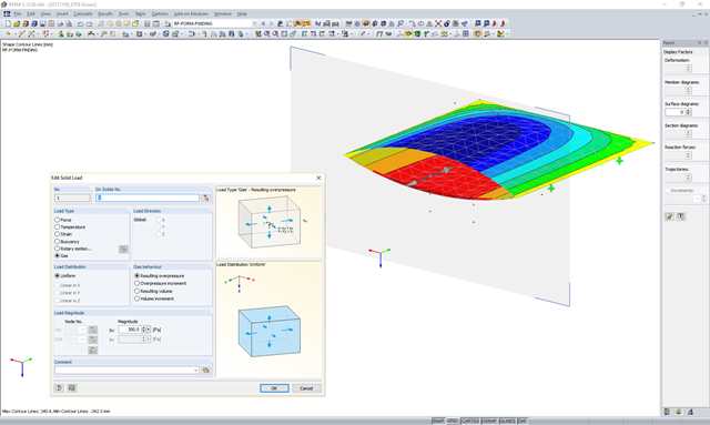
In theory, an ideal gas consists of freely moving mass particles without extension in a volume space. In this space, each particle moves at a speed in one direction. The collision of one particle with another particle or the volume limitations leads to a deflection and a change in the speed of the particles.
The efficient design of prestressed structural components requires a few additional steps that go beyond the standard reinforced concrete design, from modeling tendons to the calculation of equivalent loads to the cross-section resistance design. Therefore, it is important that the software for prestressed concrete design is structured and the navigation is possible in the program. RFEM with two add-on modules RF-TENDON and RF-TENDON Design fulfills these requirements and allows engineers to carry out the complete design of prestressed beams, frames, plates, buildings and bridges according to EN 1992-1-1 with National Annexes and SIA 262.
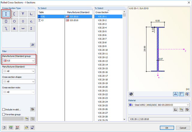
The Steel Joist Institute (SJI) previously developed Virtual Joist tables to estimate the section properties for Open Web Steel Joists. These Virtual Joist sections are characterized as equivalent wide-flange beams which closely approximate the joist chord area, effective moment of inertia, and weight. Virtual Joists are also available in the RFEM and RSTAB cross-section database.